Magnetic
mill
Magnetic mill
of the middle of the eighteenth century. A, B, C, D represents a frame
of brass or wood B for the machine, E, F, to run in. E and F are two
brass wheels, similar and equal, fixed upon a movable axis. 1, 2, 3,
etc., are a number of artificial magnets placed within the teeth of the
wheel all round, and as near each other as is possible, provided they
do not touch; their north poles at E and their south poles at F.
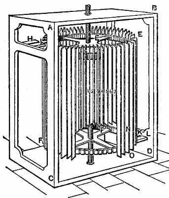
H and I are two
similar and equal magnets fixed in the brass plate, A,
C, very near each other, but not touching. K and L, two more, fixed in
the brass plate, B, D. Now, as the north pole of one magnet repels the
north pole of another magnet and attracts the south, and, inversely,
the south pole of one magnet repels the south pole of another and
attracts the north, so the south pole, I, "attracts all the north ones
at E, and the north pole, H, repels all the nor in ones at M. In like
manner, K attracts at N and L repels at O, and by this means the whole
machine, E, F, is expected to move perpetually around.
Now this would be all lovely if magnets did not attract in more than one direction. Many American inventors have tried the same principle over and over, only to find their wheel standing still, and have then sighed for some medium which, interposed between a magnet and its armature, would prevent attraction while thus interposed.
Now this would be all lovely if magnets did not attract in more than one direction. Many American inventors have tried the same principle over and over, only to find their wheel standing still, and have then sighed for some medium which, interposed between a magnet and its armature, would prevent attraction while thus interposed.
From: Gardner D. Hiscox, M.E., Mechanical Appliances and Novelties of Construction (1927), Norman W. Henley Publ. Co.