Geared
motive power
a is the axis or shaft on which the
wheels are all mounted; each wheel consists of two parallel rims, b. b, each of which is connected by
radial arms, c, to a boss, d, keyed on the axis, a; the working parts of each wheel
are mounted between the rims and arms thereof, but the outer rim, boss,
and radial arms are removed in the figure in order that the working may
be fully shown.
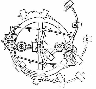
It must be
understood that the pivots or axis, j,
j, n, t, hereinafter
referred to, on which certain parts are mounted, are supported by and
extend between the two parallel rims, radial arms, and bosses of the
wheel, b, c, d. e, e are curved arms working on axes
or pivots, j,
fixed in the rims; each arm carries weights, g, g, held in place by
adjusting screws g'. Each
arm, e, terminates at its
innermost end in a
wheel, h, toothed on a portion of its periphery, through which the
weight, v, forces the
weights, g, outward at the
right-hand side of the
wheel, causing a preponderance of weight on that side.
(Subsection 928, from
p.371)
From: Gardner D. Hiscox, M.E., Mechanical Appliances and Novelties of Construction (1927), Norman W. Henley Publ. Co.