Differential
weight by flotation
Weights
descending through air force themselves by their weight into a liquid
and rise by flotation on the other side of the U-shaped chamber.
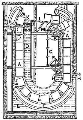
A represents
the blocks; B is the hexagon-shaped wheel; C is the
endless chain, which remains attached to the wheel by means of its
pointed hooks; E is the receptacle; F is the square wheel from which
the chain, C, at the bottom of its course is detached to reascend round
the wheel B; G, rollers, of which there are four, made of India rubber
or other elastic material, placed at the entrance of the receptacle E;
and H is the India-rubber angle pieces, also placed at the entrance,
between which rollers, G, and angle pieces, H, pass with slight
friction the blocks, after being disengaged from the chain C. These
blocks, A, angle pieces, H, and rollers, G, being in close contact,
form a stoppage, so that the water can not issue, and are pushed and
moved forward by the blocks which descend after them. I is the endless
band, resting on supports, J, fixed to the inside of the receptacle,
supporting the blocks and moving with them. The blocks, when in the
vertical part of the receptacle, are conducted by four wires, one on
each of their four sides. K is a roller upon which tilt the blocks,
guided by the endless band when on the top of the receptacle to leave
the same; L, friction rollers, on which fall and roll the blocks after
having tilted, in order to reach the hexagon wheel B.
(Subsection 952, from
p.381)
From: Gardner D. Hiscox, M.E., Mechanical Appliances and Novelties of Construction (1927), Norman W. Henley Publ. Co.