Air-buoyed
wheel
A is a cistern
of water filled as high as line R; C are six bladders, communicating by
the tubes, D, with the hollow axle E, which axle is connected with the
bellows, F, by the pipe G. H is a crank, connected with the crank, I,
by the rod K. L is a bevel wheel, M a pinion, N its shaft. O is a crank
attached to the bellows, F, by the rod P. Q are valves with projecting
levers. R and S are two projecting knobs. T is a hole in the axle, E,
forming a communication with it and the lowermost bladder.
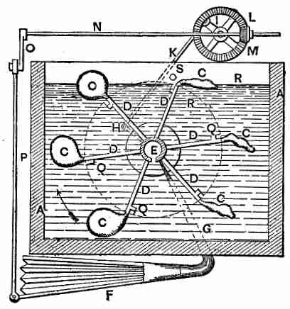
The axle, E,
being put in motion, is expected to carry round the
bladders and tables, and by the cranks, H and I, and the connecting
rod, K, cause the wheel, L, to revolve, which, communicating a similar
motion to the pinion, M, shaft, N, and crank, O, works the bellows, F,
from which the air enters the axle, E, by the tube, G, and passing
through the hole in it at T, enters the lower bladder, C, by the tube
D; this bladder being thus rendered lighter than the space it
occupies, ascends, bringing the bladder behind it over the hole in the
axle, T, in like manner, and which is thereby expected to gain an
ascending power, producing a similar effect on the one behind it. When
one of the bladders arrives at the knob, S, the lever of the valve, Q,
strikes against it and opens the valve; when the bladder arrives at C
and begins to descend, its pressure on the water drives out the air;
the knob, R, then closes the valve, Q, and prevents the entrance of any
water into the bladder; by this contrivance, three of the bladders were
expected to be alternately full and empty, according as they passed
over the hole T or the knob S.
The reason assigned for the failure of this machine was the friction, the old invincible enemy of perpetual-motion seekers.
The reason assigned for the failure of this machine was the friction, the old invincible enemy of perpetual-motion seekers.
(Subsection 957, from p.384)
From: Gardner D. Hiscox, M.E., Mechanical Appliances and Novelties of Construction (1927), Norman W. Henley Publ. Co.