Tilting
tray and ball
This invention
consists in the arrangement of an annular tilting tray, which forms the
orbit for a revolving ball, in combination with a supporting platform,
and with a lever which extends into the tray and connects with a shaft,
to which motion is to be imparted in such a manner that, by continually
changing the position of the tray, the ball is caused to rotate therein
without interruption, and by the action of the rotating ball on the
lever the desired motion is imparted to the shaft, which connects with
the working mechanism to be driven.
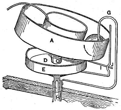
A represents a
tray, which forms an annular path for the ball B. This
tray is made of sheet metal, or any other suitable material, and its
diameter is about four times that of the ball B. It is supported in its
center by a rod, which connects, by a ball-and-socket joint, C, with a
platform, D, so that said tray can be readily tilted in any desired
direction. From the edge of the platform, D, rises a circular rim, E,
which prevents the tray from being tilted any lower than desirable. U.
S. patent, 1868.
(Subsection 933, from
p.373)
From: Gardner D. Hiscox, M.E., Mechanical Appliances and Novelties of Construction (1927), Norman W. Henley Publ. Co.