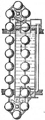
23. Perpetual Motion
Chain pump type
A series of
balls placed parallel to each other are hinged or linked together in a
similar manner as the buckets of a chain pump; this chain of floats is
passed over two sets of pulleys or disks fixed to two horizontal
shafts, the one placed vertically above the other, the said pulleys
being formed to suit the diameter of the floats.
One-half of
this chain of floats passes through the center of the tank
holding the water or other fluid, and the other half passes outside the
tank through the air. The floats, when in motion, enter through the
bottom of the tank, and rise up by their buoyancy through the water;
they then pass round the top pulley, descend outside the tank, and,
passing over the bottom pulley, again enter the tank, and so on. If
cylindrical floats are used, as described, they are fixed on the
connecting links half a diameter or more apart from each other. An
absurd device is described in this invention of 1865, for opening and
closing the entering and exit valves of the chamber and the use of
compressed air for operating them.
(Subsection 955, from
p.383) From: Gardner D. Hiscox, M.E., Mechanical Appliances and Novelties of Construction (1927), Norman W. Henley Publ. Co.


Nature bears long with those who wrong her. She is patient under abuse. But when abuse has gone too far, when the time of reckoning finally comes, she is equally slow to be appeased and to turn away her wrath. (1882) --
Nathaniel Egleston, who was writing then about deforestation, but speaks equally well about the danger of climate change today.
 Carl Sagan
: In science it often happens that scientists say, 'You know that's a really good argument; my position is mistaken,' and then they would actually change their minds and you never hear that old view from them again. They really do it. It doesn't happen as often as it should, because scientists are human and change is sometimes painful. But it happens every day. I cannot recall the last time something like that happened in politics or religion. (1987) ...
(more by Sagan) Albert Einstein: I used to wonder how it comes about that the electron is negative. Negative-positive—these are perfectly symmetric in physics. There is no reason whatever to prefer one to the other. Then why is the electron negative? I thought about this for a long time and at last all I could think was “It won the fight!” ...
(more by Einstein) Richard Feynman: It is the facts that matter, not the proofs. Physics can progress without the proofs, but we can't go on without the facts ... if the facts are right, then the proofs are a matter of playing around with the algebra correctly. ...
(more by Feynman)