UNITED
STATES PATENT OFFICE.
HENRY
BLAIR, OF
GLEN ROSS, MARYLAND.
SEED-PLANTER.
Specification of Letters Patent No. X8447,
dated October 14, 1834
[This
text has been copied from a patent record that is handwritten
(on behalf of Henry Blair). The text as transcribed may contain errors,
and does contain gaps, signified with question marks, where the
original was illegible. A link to images of the handwritten patent is
provided at the end.]
To all to whom these
presents shall concern:
Be it known that I, Henry Blair of Glen
Ross in the county of Montgomery, and the State of Maryland, have
invented a new and useful improvement in the machine for planting corn,
called the corn planter, and that the following is a full and exact
description of the construction and operation of the same, as invented
or improved by me.—
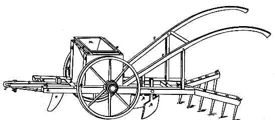
The frame of the machine is made as
follows. Two side pieces four feet six inches long ? ? two
cross pieces being tenoned into them, one at ten inches from the end
that will make the front of the machine, and the other at fourteen
inches from the other end or back; the timber of which this frame is
made is three by four inches. The beam to which the horse is to be
attached, is twenty inches in length, tenoned into the front cross
piece, in the middle between the two side pieces, and there is a brace
piece of timber, one by five inches, which passes through a mortise cut
into the beam. The ends of this piece are tenoned into the side pieces
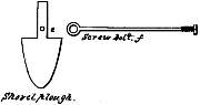
within two inches of their ends. To this beam is affixed a shovel
plough to make the furrow, the plough bar passes through the beam
sideways between the front cross piece and the brace above mentioned,
and is fastened on the top with a ?. A ? ? passes thru’ the
plough bar, made fast on the front with ? and screws; and the other end
has a hole through which passes the clevis bolt; the end of the beam is
provided with a ? ? to which is ? a ?
On the top of the two side pieces are
fastened two head blocks fourteen inches long, five and a half high and
three thick. They are tenoned into the side pieces within sixteen
inches of the front and a hole is cut through each, to receive a
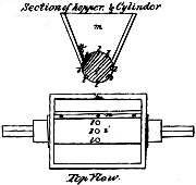
cylinder hereafter mentioned. The dropping cylinder is six inches in
diameter, between the head blocks and at each end there is a space of
three inches in length that is reduced to four inches diameter which
forms the bearings of the cylinder and work in head blocks above
mentioned; it then extends six inches (on each side) out side of the
head blocks, and is there permanently attached to wheels of two feet
six inches in diameter. There are holes in the cylinder on its
periphery sufficiently large to hold two, three or four grains of corn;
these holes may be of any number as the number of the holes, and the
diameter of the wheels will regulate the distance at which the corn is
to be dropped. A box or hopper is constructed immediately above the
cylinder, which covers about one third of its diameter, and extends the
whole length of the cylinder between the head blocks. This box or
hopper can be made to hold two or three gallons. The front part of this
hopper, that is, the side towards which the cylinder revolves, is
provided with a bar of iron extending the whole length of the hopper,
one inch wide and a quarter of an inch thick, bevelled to an edge from
the top; the lower surface of this iron hard rides on the cylinder to
prevent the grains of corn from crowding in between the cylinder and
the edge of the box or hopper.
There are two wooden braces which are
made fast to the front and back of the hopper, by means of ? ? that
extend from one head block to the other and are provided with a ? at
each end so arranged as that when either the surface of the cylinder or
the edge of the hopper wears out by turning the ? ? edge of the hopper
can be made to rest on the surface of the cylinder. Between the
cylinder and the back cross piece is to be attached by means of screw
bolts to the inside of the two side pieces two shovels made right and
left ?? the earth into a ridge. Eight inches behind the back cross
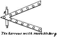
piece is a wooden … ??…. To
this ? ? is attached a harrow made of two pieces of wood, put together
in a triangle having its base open and its apex attached to the bar
just mentioned. The teeth which are inserted into the harrow are nine
inches long at the apex of the triangle and increase in length until
they reach eleven inches at the base of the triangle. The back part of
this harrow will be at liberty to play up and down, having its front
part attached to the ? bar. The handles are four feet long, having
their lower ends let into the lower part of the head blocks and their
upper ends elevated to two feet seven inches above the frame; they are
framed in the usual manner.
Operation:
When the horse draws the machine the shovel plough makes a furrow to
receive the grain; the cylinder in revolving with the wheels to which
it is permanently attached, catch the grains in the holes (which are
made on its periphery) as they pass through the hopper and lets them
drop into the furrow; the ? then throw the earth into a ridge over the
grains & the harrow passing over it levels the earth and
carries the large clods and stones away. The proportions herein stated
may be varies at pleasure.
What I claim as new and as my invention
and for which I ask Letters Patent, is, the general arrangement and
combination of the several parts. As a further illustration of my
invention, I refer the model and drawing which accompany this.
In testimony that the above is a full
and exact description of the construction and operation of my machine
as invented or improved by me. I have hereunto subscribed my hand this
first day of September in the year of our Lord one thousand eight
hundred & thirty four.
More Information:
Corn
Planting Machine short
article from The
Mechanics' Magazine (1836).
Cotton
Planter, Henry Blair's Patent 15