UNITED STATES
PATENT
OFFICE.
JOSEPHINE G.
COCHRAN, OF SHELBYVILLE, ILLINOIS.
DISH-WASHING
MACHINE
SPECIFICATION forming part of Letters
Patent No. 355,139, dated December 28,1886.
Application
filed December 31, 1885. Serial No. 187,276. (No model)
To all whom it may concern:
Be it known that I, JOSEPHINE
G. COCHRAN,
a citizen of the United States, residing at Shelbyville, in the county
of Shelby and State of Illinois, have invented a new and useful
Improvement in Dish-Washing Machines, of which the following is a
specification.-
My invention relates to an improvement
in machines
for washing dishes, in which a continuous stream of either soap-suds or
clear hot water is supplied to a crate holding the racks or cages
containing the dishes while the crate is rotated so as to bring the
greater portion thereof under the action of the water.
The improvement will first be described
with
reference to the accompanying drawings, and then be more particularly
pointed out in the claims.
[Click
on any thumbnail below to enlarge]
 Figure I represents my improved dish-washing machine in front
elevation, parts being broken away to exhibit interior portions. Fig.
II is a vertical sectional view of the same, looking from the opposite
side. Fig. III shows a bottom view and a side elevation of a portion of
the preferred form of the water-spray pipe. Fig. IV is an end elevation
of the crate. Fig. V is a side elevation of the supporting-bracket for
one end thereof. Fig. VI is a perspective view of the driving disk and
shaft of said crate. Fig. VII is a side elevation of the machine, part
of the casing being broken away to show one of the pumps. Fig. VIII is
a detail view of part of the crate-operating mechanism. Fig. IX is a
front elevation, and Fig. X a side elevation, of a rack or cage for
knives, forks, and spoons. Figs. XI to XV, inclusive, are side and end
elevations and plan of two forms of racks or cages for dishes, plates,
&c.
Figure I represents my improved dish-washing machine in front
elevation, parts being broken away to exhibit interior portions. Fig.
II is a vertical sectional view of the same, looking from the opposite
side. Fig. III shows a bottom view and a side elevation of a portion of
the preferred form of the water-spray pipe. Fig. IV is an end elevation
of the crate. Fig. V is a side elevation of the supporting-bracket for
one end thereof. Fig. VI is a perspective view of the driving disk and
shaft of said crate. Fig. VII is a side elevation of the machine, part
of the casing being broken away to show one of the pumps. Fig. VIII is
a detail view of part of the crate-operating mechanism. Fig. IX is a
front elevation, and Fig. X a side elevation, of a rack or cage for
knives, forks, and spoons. Figs. XI to XV, inclusive, are side and end
elevations and plan of two forms of racks or cages for dishes, plates,
&c.
1 may represent a metallic or wooden
box, having a
forward extension providing two tanks, 2, wherein are situated two
force-pumps, 3 4. The lower part of the box is divided into two
compartments for the height of the forward extension 2 by a vertical
diaphragm, 5, one of the pumps 3 4 being situated in each compartment.
This device, with the aid of the movable bottom 36 for box 1,
hereinafter described, enables the complete separation of the water in
one side of the machine from the other, the soap-suds and clear hot
water, when respectively used, being each returned to its appropriate
force-pump and used over and over again until it needs renewing.
6 are apertures for allowing water to
enter the
lower cylinders, 3 4, of the pumps. These apertures may be valved; or a
single valved aperture may be substituted therefor.
 7 are water-jet pipes extending from the pumps 3 4 at each side of the
box 1, and terminating at the top in a horizontal portion, which is
either slotted throughout, as shown in, Fig. II, or provided with a
series of jet-holes, as shown in Fig. III.
7 are water-jet pipes extending from the pumps 3 4 at each side of the
box 1, and terminating at the top in a horizontal portion, which is
either slotted throughout, as shown in, Fig. II, or provided with a
series of jet-holes, as shown in Fig. III.
8 are air-cushioning chambers in the
force-pipes 7.
9 are pump-pistons having rods 10,
provided with
racks 11 at their upper ends. Strips 12, cast or formed on the rack 11,
engage over pins or rollers 13, supported from the cross-bar 14 of the
box, and thus guide the piston-rods 10 in vertical paths.
15 is the main operating-lever of the
machine,
pivoted at 16 to the frame of the box, and provided at its other end
with a handle, 17. Pivoted to the lever 15, at 18 18, are two
segment-racks, 19 19, connected by rods 20, near their upper ends, with
the opposite ends of the vertical lever 21, pivoted at 22 to the main
lever 15.
It will be seen that by operating the
small lever 21
either of the racks 19 may be thrown against its appropriate piston-rod
rack 11, the other segment-rack 19 being simultaneously detached. The
lever 15 being then operated, it actuates that pump-piston whose rack
is for the time being engaged by one of the segment-racks 19.
Simultaneously with the shifting of the operating-lever from one pump
to the other, I shift the movable bottom 36, before mentioned, so as to
supply water to the tank 2 at one or the other side of the box. This is
accomplished by the following mechanism:
23 is a lever, pivoted at 24 to the
frame of the
box, and having curved arms 25, which occupy positions over one or
other of the racks 11, so that upon the operation of one of such racks
by the mechanism just described it will at the first stroke, if one of
the arms of the lever 23 be at the time above it, throw the lever 23
over its fulcruming-point 24, and thus allow said rack to reciprocate
without again coming in contact with the arm 25.
26 is a rod connecting the lever 23 with
a crank, 27.
28 is a pin or bolt hinged to the
connection between
the rod 26 and crank 27 at its upper end, and sliding in a bracket, 29,
on the box at its lower end. A spring, 30, surrounding the pin 28 bears
on the bracket 29 and crank 27, so as to insure the throwing of such
crank, and consequently of the lever 23, to its extreme position as
soon as the knuckle-joint at 31 passes to one or the other side of a
straight line drawn between the pivot-pin 32 of crank 27 and the center
of bracket 29. The pivot-rod 32 is rigidly connected interiorly of the
box to a second crank, 33, and thus, by connecting rod 34 with arms 35
of the movable bottom 36, a ledge, 37, is fixed to each side of the
box, immediately over the path of the movable bottom 36, so as to
direct water falling down the sides of the box onto the bottom.
From the above-described construction it
is apparent
that as soon as one or other of the pumps is operated the movable
bottom is automatically shifted from the appropriate side, so that
water is returned to the tank of the pump being used and warded off
from the other tank.
An oil or other stove or heater: may be
placed under
one or other of the tanks 2 2, which it is preferred to employ for
containing the hot water.
38, Figs. II and IV, is a cylindrical
wire crate,
wherein the cages containing the dishes to be cleaned are placed.
 39 is a door at one side of the crate, having suitable means of
fastening. (Not here shown.) A circular trunnion, 40, at one end of the
crate 38 is supported in a bracket, 41, Fig.V, which is fixed to the
side of the box and open at top, so as to allow the crate to be readily
removed. At its other end the crate has a square projection or trunnion
for engaging in a similarly-shaped socket, 42, Fig. VI, on the inner
end of a shaft, 43, Fig. II, journaled in the wall of the box and in a
bracket, 44.
39 is a door at one side of the crate, having suitable means of
fastening. (Not here shown.) A circular trunnion, 40, at one end of the
crate 38 is supported in a bracket, 41, Fig.V, which is fixed to the
side of the box and open at top, so as to allow the crate to be readily
removed. At its other end the crate has a square projection or trunnion
for engaging in a similarly-shaped socket, 42, Fig. VI, on the inner
end of a shaft, 43, Fig. II, journaled in the wall of the box and in a
bracket, 44.
45 is a friction-disk fixed on the shaft
43 so as to revolve in a vertical plane.
46 is a vertical rock-shaft journaled in
brackets
47, and having a horizontal crank-arm, 48, connected by rod 49 with the
main operating-lever 15, and having additional horizontal crank-arms,
50, carrying friction-clutches 51. The said clutches engage with
opposite sides of the disk 45 in one direction of their motion and not
the other, so as to alternately grasp and rotate the same.
 During the continuous operation of the lever 15, and while one of the
pumps 3 4 is supplying a steady stream of water through the pipes 7 to
dishes in the crate 38, the shaft 46 is by its connection with the
lever 15 rocked, and the disk 45 and crate 38 slowly rotated, so that
all the dishes in the crate are exposed to the stream of water and
cleaned. After they are thoroughly cleaned by soap-suds from one pump,
the racks 11 19 are shifted so as to bring the other clear-hot-water
pump into operation, thus automatically uncovering the proper tank in
the bottom of the box. By this means a stream of hot rinsing-water is
poured onto the dishes until they are perfectly clean. When they are
dry from their own heat they are ready to be put away or immediately
again used upon the table, no draining or drying being necessary after
their removal from the machine.
During the continuous operation of the lever 15, and while one of the
pumps 3 4 is supplying a steady stream of water through the pipes 7 to
dishes in the crate 38, the shaft 46 is by its connection with the
lever 15 rocked, and the disk 45 and crate 38 slowly rotated, so that
all the dishes in the crate are exposed to the stream of water and
cleaned. After they are thoroughly cleaned by soap-suds from one pump,
the racks 11 19 are shifted so as to bring the other clear-hot-water
pump into operation, thus automatically uncovering the proper tank in
the bottom of the box. By this means a stream of hot rinsing-water is
poured onto the dishes until they are perfectly clean. When they are
dry from their own heat they are ready to be put away or immediately
again used upon the table, no draining or drying being necessary after
their removal from the machine.
 To strain off the larger impurities a perforated diaphragm may be
placed under the movable bottom of the tank, as shown in Fig. II at 72.
To strain off the larger impurities a perforated diaphragm may be
placed under the movable bottom of the tank, as shown in Fig. II at 72.
A rack or cage for knives and similar
articles is
shown in Figs. IX and X. It consists of a frame, 52, preferably of
wire, to the end plates, 53, of which are secured the ends of the bars
54, which support a number of spring-clamps, 55. Articles to be washed
are laid upon the bars 56 of the frame, and the clamp-bars 54 are then
placed over them and are held down by the racks 57, engaging with
projections 58 on the ends of the bars 54.
 In Figs. XI and XII are shown side and end elevations of a rack for
plates, saucers, &c. The outer web of the cage is made of wires
59,
so as to be practically rectangular. From each corner wire projects
into the case a series of wires, 60, which for the major part of their
length are parallel with the outer wires of the cage, and which serve
as supports for the plates placed in the cage in vertical position.
Frames 61, having vertical wires 62, which may project, as shown, and
may be similar to those 60, may be placed between any two of the wires
60 at the ends of the cage, and thus divide the cage into two parts,
and at the same time afford an interior bearing for the plates and
saucers that are placed within the cage. For articles that require a
spring-support below, an interior cushion is provided in one of the
compartments of the cage, consisting of springs 63, united by
longitudinal and cross bars 64. Handles 65 are provided at each end of
the cage for convenience in carrying.
In Figs. XI and XII are shown side and end elevations of a rack for
plates, saucers, &c. The outer web of the cage is made of wires
59,
so as to be practically rectangular. From each corner wire projects
into the case a series of wires, 60, which for the major part of their
length are parallel with the outer wires of the cage, and which serve
as supports for the plates placed in the cage in vertical position.
Frames 61, having vertical wires 62, which may project, as shown, and
may be similar to those 60, may be placed between any two of the wires
60 at the ends of the cage, and thus divide the cage into two parts,
and at the same time afford an interior bearing for the plates and
saucers that are placed within the cage. For articles that require a
spring-support below, an interior cushion is provided in one of the
compartments of the cage, consisting of springs 63, united by
longitudinal and cross bars 64. Handles 65 are provided at each end of
the cage for convenience in carrying.
 Figs. XIII, XIV, and XV are respectively side elevation, plan, and end
elevation of a rack for glass and other hollow articles. The rack or
cage is made of wires 66, and is divided into two parts which are
hinged together, as shown at 67; but they may be fixed so as to form a
rectangular cage by means of catches 68. Within each compartment of
this cage a number of spiral springs, 69, are arranged upon a movable
frame, 70, and so adapted as to surround the necks and bases of hollow
articles, and by pressing them gently against the top and bottom of the
cage hold them in position while the cage is being turned within the
crate of the dish-washing machine. To increase their power of
maintaining the dishes in upright position, the lower ends of the
springs 69 are preferably connected by links 71.
Figs. XIII, XIV, and XV are respectively side elevation, plan, and end
elevation of a rack for glass and other hollow articles. The rack or
cage is made of wires 66, and is divided into two parts which are
hinged together, as shown at 67; but they may be fixed so as to form a
rectangular cage by means of catches 68. Within each compartment of
this cage a number of spiral springs, 69, are arranged upon a movable
frame, 70, and so adapted as to surround the necks and bases of hollow
articles, and by pressing them gently against the top and bottom of the
cage hold them in position while the cage is being turned within the
crate of the dish-washing machine. To increase their power of
maintaining the dishes in upright position, the lower ends of the
springs 69 are preferably connected by links 71.
Having thus described my invention, the
following is
what I claim as new therein and desire to secure by Letters Patent:
1. In combination with the box of a
dish-washing
machine, receptacles or tanks connected therewith and a movable bottom
adapted to cover one receptacle and deflect water falling thereon into
the other, substantially as set forth.
2. In combination with the box of a
dish-washing
machine, an operating-lever, pumps, racks on the piston-rods of said
pumps, pivoted racks supported on the main operating-lever, and means
for throwing one or other of said pivoted racks into engagement with
the rack on one of the piston-rods, substantially as set forth.
3. In combination with the box of a
dish-washing
machine, partitioned as shown, two pumps, means of connecting one or
other at will with the operating handle or lever, a movable bottom for
the box, and connections therefrom to the pump-pistons, whereby it is
automatically shifted as each pump is alternately operated,
substantially as set forth.
4. In combination with the box 1, the
pump
piston-rods and a lever for operating the same, a lever, 23, pivoted to
the box, having arms 25, projecting over the piston-rods, and a movable
bottom wherewith said lever 23 is connected, substantially as set forth.
5. In combination with the lever 23 and
means for
shifting the same, a crank, 27, a rod, 26, connecting said crank and
lever, a movable bottom operated by said crank, and a spring-bolt, 28
29 30, for throwing said crank and lever to its extreme positions to
one side or the other, substantially as set forth.
6. The combination, with a box and
rotary crate, of
two pumps having independent discharge-pipes, a hinged lever adapted to
engage either pump-rod, and a connection, substantially as described,
by which the lever ro-tates the crate while connected with either pump.
7. In combination with a horizontal
rotary
dish-crate, a horizontal shaft connected thereto, a friction-disk
thereon, a vertical rock-shaft carrying friction-clutches engaging with
said disk, and an operating-lever connected with said vertical
rock-shaft, substantially as set forth.
8. In combination with a rotary
dish-crate having a
square trunnion at one end for engaging with the operating-shaft and a
circular trunnion at the other, a bracket fixed to the box having
bearing for the circular trunnion, open at top to permit the removal of
the crate, substantially as set forth.
9. A knife-and-fork rack or cage for
dish-washing
machines, consisting of a frame, 52, provided with end plates, 53,
having racks 57, the bars 54, having projections 58, the bars 56, on
which the articles are placed, and spring-clamps 55, substantially as
described.
10. A plate-and-saucer rack or cage for
dish-washing
machines, consisting of an approximately rectangular wire cage having
an outer web of wires, 59, and the inwardly-projecting vertical wires
60, extending from the corners around the sides and ends, substantially
as described.
11. A plate-and-saucer rack or cage for
dish-washing
machines, consisting of an approximately rectangular wire cage having
an outer web of wires, 59, the inwardly-projecting vertical wires 60,
extending from the corners around the sides and ends, and the interior
frames, 61, having vertical wires 62, similar to the
inwardly-projecting vertical wires, substantially as described.
12. A rack for hollow articles,
consisting of two
wire cages having wires 66, hinged together, means for securing them
together at the front, and movable frame 70, spiral springs 69, and
connecting links 71, substantially as described.
JOSEPHINE G.
COCHRAN.
Witnesses:
J. WM.
LLOYD,
R. L. GARIS.
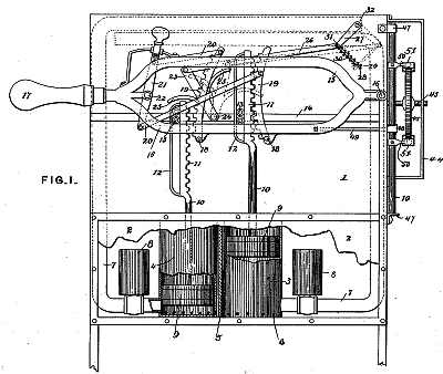
 Figure I represents my improved dish-washing machine in front
elevation, parts being broken away to exhibit interior portions. Fig.
II is a vertical sectional view of the same, looking from the opposite
side. Fig. III shows a bottom view and a side elevation of a portion of
the preferred form of the water-spray pipe. Fig. IV is an end elevation
of the crate. Fig. V is a side elevation of the supporting-bracket for
one end thereof. Fig. VI is a perspective view of the driving disk and
shaft of said crate. Fig. VII is a side elevation of the machine, part
of the casing being broken away to show one of the pumps. Fig. VIII is
a detail view of part of the crate-operating mechanism. Fig. IX is a
front elevation, and Fig. X a side elevation, of a rack or cage for
knives, forks, and spoons. Figs. XI to XV, inclusive, are side and end
elevations and plan of two forms of racks or cages for dishes, plates,
&c.
Figure I represents my improved dish-washing machine in front
elevation, parts being broken away to exhibit interior portions. Fig.
II is a vertical sectional view of the same, looking from the opposite
side. Fig. III shows a bottom view and a side elevation of a portion of
the preferred form of the water-spray pipe. Fig. IV is an end elevation
of the crate. Fig. V is a side elevation of the supporting-bracket for
one end thereof. Fig. VI is a perspective view of the driving disk and
shaft of said crate. Fig. VII is a side elevation of the machine, part
of the casing being broken away to show one of the pumps. Fig. VIII is
a detail view of part of the crate-operating mechanism. Fig. IX is a
front elevation, and Fig. X a side elevation, of a rack or cage for
knives, forks, and spoons. Figs. XI to XV, inclusive, are side and end
elevations and plan of two forms of racks or cages for dishes, plates,
&c. 7 are water-jet pipes extending from the pumps 3 4 at each side of the
box 1, and terminating at the top in a horizontal portion, which is
either slotted throughout, as shown in, Fig. II, or provided with a
series of jet-holes, as shown in Fig. III.
7 are water-jet pipes extending from the pumps 3 4 at each side of the
box 1, and terminating at the top in a horizontal portion, which is
either slotted throughout, as shown in, Fig. II, or provided with a
series of jet-holes, as shown in Fig. III. 39 is a door at one side of the crate, having suitable means of
fastening. (Not here shown.) A circular trunnion, 40, at one end of the
crate 38 is supported in a bracket, 41, Fig.V, which is fixed to the
side of the box and open at top, so as to allow the crate to be readily
removed. At its other end the crate has a square projection or trunnion
for engaging in a similarly-shaped socket, 42, Fig. VI, on the inner
end of a shaft, 43, Fig. II, journaled in the wall of the box and in a
bracket, 44.
39 is a door at one side of the crate, having suitable means of
fastening. (Not here shown.) A circular trunnion, 40, at one end of the
crate 38 is supported in a bracket, 41, Fig.V, which is fixed to the
side of the box and open at top, so as to allow the crate to be readily
removed. At its other end the crate has a square projection or trunnion
for engaging in a similarly-shaped socket, 42, Fig. VI, on the inner
end of a shaft, 43, Fig. II, journaled in the wall of the box and in a
bracket, 44. During the continuous operation of the lever 15, and while one of the
pumps 3 4 is supplying a steady stream of water through the pipes 7 to
dishes in the crate 38, the shaft 46 is by its connection with the
lever 15 rocked, and the disk 45 and crate 38 slowly rotated, so that
all the dishes in the crate are exposed to the stream of water and
cleaned. After they are thoroughly cleaned by soap-suds from one pump,
the racks 11 19 are shifted so as to bring the other clear-hot-water
pump into operation, thus automatically uncovering the proper tank in
the bottom of the box. By this means a stream of hot rinsing-water is
poured onto the dishes until they are perfectly clean. When they are
dry from their own heat they are ready to be put away or immediately
again used upon the table, no draining or drying being necessary after
their removal from the machine.
During the continuous operation of the lever 15, and while one of the
pumps 3 4 is supplying a steady stream of water through the pipes 7 to
dishes in the crate 38, the shaft 46 is by its connection with the
lever 15 rocked, and the disk 45 and crate 38 slowly rotated, so that
all the dishes in the crate are exposed to the stream of water and
cleaned. After they are thoroughly cleaned by soap-suds from one pump,
the racks 11 19 are shifted so as to bring the other clear-hot-water
pump into operation, thus automatically uncovering the proper tank in
the bottom of the box. By this means a stream of hot rinsing-water is
poured onto the dishes until they are perfectly clean. When they are
dry from their own heat they are ready to be put away or immediately
again used upon the table, no draining or drying being necessary after
their removal from the machine. To strain off the larger impurities a perforated diaphragm may be
placed under the movable bottom of the tank, as shown in Fig. II at 72.
To strain off the larger impurities a perforated diaphragm may be
placed under the movable bottom of the tank, as shown in Fig. II at 72. In Figs. XI and XII are shown side and end elevations of a rack for
plates, saucers, &c. The outer web of the cage is made of wires
59,
so as to be practically rectangular. From each corner wire projects
into the case a series of wires, 60, which for the major part of their
length are parallel with the outer wires of the cage, and which serve
as supports for the plates placed in the cage in vertical position.
Frames 61, having vertical wires 62, which may project, as shown, and
may be similar to those 60, may be placed between any two of the wires
60 at the ends of the cage, and thus divide the cage into two parts,
and at the same time afford an interior bearing for the plates and
saucers that are placed within the cage. For articles that require a
spring-support below, an interior cushion is provided in one of the
compartments of the cage, consisting of springs 63, united by
longitudinal and cross bars 64. Handles 65 are provided at each end of
the cage for convenience in carrying.
In Figs. XI and XII are shown side and end elevations of a rack for
plates, saucers, &c. The outer web of the cage is made of wires
59,
so as to be practically rectangular. From each corner wire projects
into the case a series of wires, 60, which for the major part of their
length are parallel with the outer wires of the cage, and which serve
as supports for the plates placed in the cage in vertical position.
Frames 61, having vertical wires 62, which may project, as shown, and
may be similar to those 60, may be placed between any two of the wires
60 at the ends of the cage, and thus divide the cage into two parts,
and at the same time afford an interior bearing for the plates and
saucers that are placed within the cage. For articles that require a
spring-support below, an interior cushion is provided in one of the
compartments of the cage, consisting of springs 63, united by
longitudinal and cross bars 64. Handles 65 are provided at each end of
the cage for convenience in carrying. Figs. XIII, XIV, and XV are respectively side elevation, plan, and end
elevation of a rack for glass and other hollow articles. The rack or
cage is made of wires 66, and is divided into two parts which are
hinged together, as shown at 67; but they may be fixed so as to form a
rectangular cage by means of catches 68. Within each compartment of
this cage a number of spiral springs, 69, are arranged upon a movable
frame, 70, and so adapted as to surround the necks and bases of hollow
articles, and by pressing them gently against the top and bottom of the
cage hold them in position while the cage is being turned within the
crate of the dish-washing machine. To increase their power of
maintaining the dishes in upright position, the lower ends of the
springs 69 are preferably connected by links 71.
Figs. XIII, XIV, and XV are respectively side elevation, plan, and end
elevation of a rack for glass and other hollow articles. The rack or
cage is made of wires 66, and is divided into two parts which are
hinged together, as shown at 67; but they may be fixed so as to form a
rectangular cage by means of catches 68. Within each compartment of
this cage a number of spiral springs, 69, are arranged upon a movable
frame, 70, and so adapted as to surround the necks and bases of hollow
articles, and by pressing them gently against the top and bottom of the
cage hold them in position while the cage is being turned within the
crate of the dish-washing machine. To increase their power of
maintaining the dishes in upright position, the lower ends of the
springs 69 are preferably connected by links 71.