MICAH RUGG, OF SOUTHINGTON, CONNECTICUT.
MACHINE FOR TRIMMING THE HEADS OF BOLTS.
Specification of Letters Patent No. 2,766, dated August 31, 1842
MACHINE FOR TRIMMING THE HEADS OF BOLTS.
 To all whom it may concern:
Be it known that I, MICAH
RUGG, of Southington, in the county of
Hartford and State of Connecticut, have invented a new and useful
Improvement in the Mode and Method of Trimming the Heads of Bolts and
in the Machinery Necessary for Affecting the Same, and that the
following is a full and exact description thereof, reference being had
to the annexed drawings, making a part of this specification, in
which—
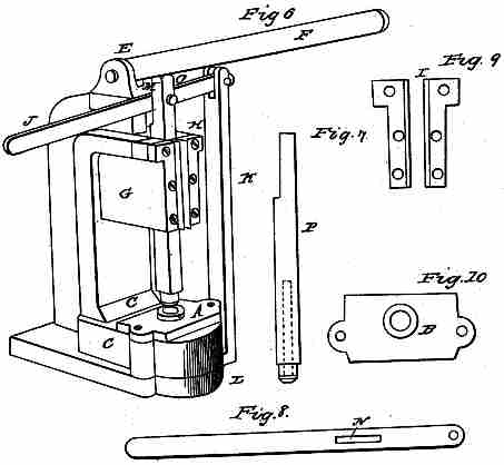
Figure 6 is a perspective view of the
machine used for trimming the
heads of bolts, a roughness being left upon the edge when the bolt is
headed.
The nature of my invention and
improvement in this machine consists in
having an upright punch or slide with a hole in the lower end of
sufficient length to admit the bolt required to be trimmed with the
head downward and resting upon a die having a perforation through the
same of the exact size of the bolt head when trimmed as may be seen at
A in Fig. 6 or B in Fig. 10.
To enable others skilled in the art to
make use of my invention and
improvement I will proceed to describe the construction, operation and
use of the trimming machine, which is as follows: The base or
foundation of the machine marked C, on the forward part of which is
placed the die with the perforated hole marked A and made part by means
of two bolts with nuts running through the base C and die A. From the
back part of the case C rises the perpendicular portion of the casting
of the machine marked D, on the top of which is cast two ear pieces or
projections marked E to receive and hold to its place the lever F by
means of a pin or bolt running through both; a forward projection from
the perpendicular part or portion of the machine is marked G, having a
groove marked H in the perspective to admit the slide or punch 0 in
perspective.
In Fig. 9 are two iron plates made fast
to the machine by means of
screws the use of which is to hold in its proper place and keep steady
the slide or punch marked O in perspective. The transverse lever J is
attached to a perpendicular post marked K, the bottom of which is made
fast to the base of the machine at L. The transverse lever J has a long
mortise at M in the perspective and at N in Fig. 8 receiving a pin that
passes through the slide or punch O in the perspective and T, Fig. 7,
allowing a slide in the movement of the machine that the slide O may be
raised and lowered in a perpendicular direction. Fig. 7 represents the
slide or punch O with the hole at the bottom to receive the bolt.
Fig. 8 represents the transverse lever J
with the mortise.
Fig. 9 represents the iron plates that
holds the slide O in the groove
H in the perspective.
Fig. 10 represents the die through which
the bolt passes when trimmed
and marked A in the perspective. In the operation of the machine place
the lever F in a perpendicular position, then raise the transverse
lever J, by which operation the slide O is raised; place the bolt in
the hollow slide O, letting the head rest over the die A. Then by means
of the lever F force down the slide or punch O that the head of the
bolt may pass through the die A, coming through the under side of the
machine with the edges perfectly trimmed off. The slide or punch may be
forced through and the bolt trimmed by the use of a screw attached to
the slide or by striking on the top with any heavy hard substance or
metal sufficiently hard to force through the bolt.
What I claim as. my invention and desire
to secure by Letters Patent is—
The combination of the hollow slide or
punch which receives and carries
the bolt in combination with the die for trimming the heads of bolts as
described.