UNITED STATES
PATENT
OFFICE.
GRANVILLE T.
WOODS, OF NEW YORK, N. Y.
AMUSEMENT APPARATUS.
SPECIFICATION forming part of Letters
Patent No. 639,692, dated December 19, 1899.
Application filed September 27, 1898. Serial No. 691,978.
(No model.)
To all whom it may concern:
Be it known that I, GRANVILLE T.
WOODS, a citizen of the United States, and a
resident of New York, in the
county of New York and State of New York, have invented a certain new
and useful Amusement Apparatus, of which the following is a
specification.
My invention relates to an amusement apparatus in which race-tracks are
used.
The object of the invention is to provide a novel and
interesting form
of amusement apparatus capable of use at summer and other resorts, at
fairs, &c., and in or out of doors. The invention comprises,
substantially, two or more tracks in suitable proximity to permit the
movement of the cars or objects on all to be readily observed at once
or from one another, a motor-driven vehicle, car, or other device for
each track moving, preferably, on suitable guides or ways, and a
suitable adjustable blind or non-indicative speed-controller for the
motor of each device, controlled and operated as hereinafter described
and claimed.
The apparatus may be constructed on a large or a small
scale, as
desired, and the moving cars or device may be capable of carrying
persons or objects or not, as desired and according to the space to be
occupied.
The motor may be of any kind, but preferably an electric
motor, and the
control may be effected either upon the car alone or at the side of the
track alone, or at both points, as hereinafter set forth. The tracks
should be of substantially the same length, and means are provided for
returning each car to the starting-point. Preferably this is done by
making each track of a shape which returns upon itself. In the case of
an electrically-driven motor it is obvious that the source of electric
power may be either upon the car or beside the track.
The controlling devices may be of any desired form adapted
to the
character of the motive power, and each is controlled by hand, being
either set originally in any desired fashion and left in adjusted
position while the race is being run or being adjusted as the judgment
of the operator may seem to dictate is best while the race is in
progress. Preferably the apparatus is so constructed that the actual
condition of the controlling device cannot be seen or judged by the
position of any of the parts, the effects alone being observable or
judged of by the observed speed or changes of speed of the car or
motor-driven device.
In every form of speed-controlling device brought out
heretofore some
provision for indication has been made whereby the operator was enabled
to see or judge the position of the parts of the controller, so that he
could foretell the effect of a given movement of the controller-handle.
In apparatus constructed or used for the purpose herein described such
a speed-controller as just described would be of little utility. A
speed-controller devoid of means whereby the condition or position of
its main operative parts could be determined while in use would be
technically called a "blind" or "non-indicative" speed-controller.
My present invention relates (in part) to a blind speed controller, and
I claim, broadly, any form of speed-controller having a blind or
concealed deceptive action. To further add to the interest, the action
of each controller may be made irregular or changeable in running
through its range of adjustment, as will be shown in the case of an
electric resistance.
My invention relates, further, to the form and relative disposition of
the tracks, the object being to have the tracks return each on itself,
to be substantially parallel to one another, and yet to be all of
substantially the same length. This part of my invention consists,
substantially, of two or more tracks each of curved form, so as to
return upon itself, and each lying partly outside and partly inside the
other or others, so as to have substantially the same length, such
tracks lying opposite or substantially parallel to one another
throughout their whole extent. For the sake of compactness I prefer to
make each track of substantially the form of the figure 8 and to make
one part of each track lie within and the other part lie without the
corresponding parallel portion of the other, as illustrated in the
accompanying drawings. The tracks may cross at different levels or on
the same level. In the latter case when equipped with railways suitable
frogs are provided at the crossing-points.
My invention consists, farther, in the novel apparatus and combinations
of apparatus hereinafter described, and then specified in the claims.
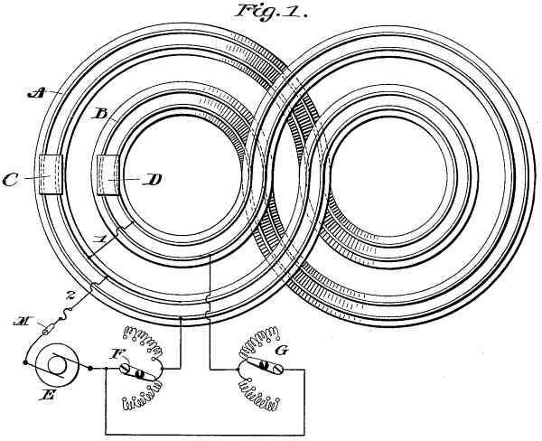
In the accompanying drawings, Figure 1 is a general diagrammatic view
illustrating my invention as carried out by means of an
electrically-propelled apparatus moving on tracks of preferred form.
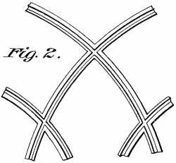
Fig. 2 shows a system of frogs that may be used at crossing-points.
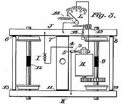
Fig. 3 shows the arrangement of apparatus that may be employed on the
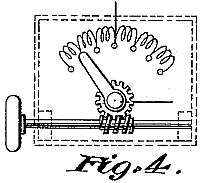
car. Fig. 4 illustrates, diagrammatically, one of the electric
controllers.
In Fig. 1 two race-tracks are shown in outline, each equipped with
rails or tracks A B, on which move cars, vehicles, or objects C D. Each
race-track, as will be seen, is of the general form of the figure 8 and
returns upon itself, so that the car on traveling over the same will
come back to its starting-point, and each, track is arranged to lie
partly within and partly without the other, so that the cars C D,
moving over the same, will in moving a circuit move approximately the
same distance, While I show tracks of the shape of the figure 8 and
also show the tracks as being approximately parallel to one another
through their whole circuit, it is not necessary that they should be so
arranged or of the particular shape shown, though the relative form and
arrangement shown are preferred. Where each track crosses itself, it
may cross at different levels or cross at the same level and be
provided at the crossing-point, with frogs for the vehicle rails or
tracks. Where each track crosses the other, it may, as shown, cross at
a different level, as indicated by the shading, although at this point
also the crossing may be at the same level and frogs be provided for
the railroad-track at the crossing. It is preferable that one track
should cross the other at a different level, though this is not
necessary, since, owing to the difference in curvature, the cars or
vehicles, unless moving at very widely different speeds, will not reach
the crossing-points at the same time, so as to cause collision.
When the system is to be operated electrically, devices and connections
should be provided as follows: E is any generator of electricity
connected at one pole to one rail of track A, which latter is connected
to one rail of track B by connection 1. The opposite pole of the
generator connects to the opposite rails of the tracks through suitable
controllers F G. As will be seen, one rail of each track or pair of
rails is used for delivering current to the motor carried by the car,
while the other rail is for use in returning the current to the
generator. Any other system of delivering current from a stationary
generator to motors on the cars C D might be employed.
Referring to Fig. 3, H typifies any car-driving electric motor operated
by the current taken from the generator E, or, if desired, by
electrical power obtained from a storage or other battery I, which may
be substituted for the generator E by shifting the switch 3 from point
5 to point 4. When the current is taken from the rails, the two sides
of the motor truck and frame and the wheels at opposite ends of the
car-axles are electrically insulated from one another, as is well
understood in the art, so that current cannot pass from one rail to the
other without passing through the motor. The points of insulation are
indicated by the figures G to 13, inclusive. When the motor is driven
by current direct from the generator E, then its terminals are
connected, respectively, through the rails and car-wheels to the sides
of the car-frame. An automatic brake 18 is so arranged that when the
motor receives operative current the brake comes off and when the
current is off the brake goes on. This may be effected by means
of an
electromagnet 19, placed in the controller-circuit and connected to the
brake-lever and acting in opposition to a spring which operates to
apply the brake. A controller L may be also placed in the circuit of
the motor on each car, as indicated by the diagram. Any or all of the
controllers maybe provided with a spring 14 or other devices for giving
the same a bias which has a tendency to hold the controller in a
certain position, which position may be one extreme of its range of
movement or any other position. The manual power exerted in moving the
controller is with or against the bias, thus rendering it more
difficult to hold the controller in any particular position. By so
constructing the controller or providing it with proper devices whereby
it will have a bias such that it will automatically assume a position
where the power will be cut off, and by combining with the apparatus a
brake the application of which is also automatically controlled by the
position of said handle, I secure this important result—to wit, that
in case the hand ceases to govern the car when the controller-handle is
away from its starting-point the power will be cut off automatically
and the brake will be automatically applied, so as to stop the car. The
type of controller here shown is one which operates by varying the
resistance in the circuit of the motor. As will be seen, the sections
of resistance are so arranged and connected that the action of the
controller-arm is irregular or changeable in the movement thereof or in
its progressive movement so cooperates with said resistances that the
delivery of power to said device is first permitted or increased and
then cut off or reduced, or vice versa—that is to say, starting from
one extreme of movement it will throw out resistance at first and then
as it continues its movement will begin to throw it in. This irregular
or changeable action might be produced by other diversifications in the
usual arrangement of resistances and repeated and varied any number of
times through the whole range of movement, and the parts being
concealed by a blind or shield, as indicated by the outline in Fig. 4,
the operator when manipulating the controller during the progress of
the race must depend entirely upon his judgment and observation of the
movement of the car or device C or D to determine how to move the
controlling device. To still further render it difficult to judge of
the actual position of the operating portion of the controlling device
by the position of a controlling-handle, the controller-arm may be
operated by a non-indicative knob and worm and screw arrangement, as
illustrated in Fig. 4, the knob alone being exposed to view and being
operated blindly by a turning or twisting movement to actuate the
controller.
One manner of using the apparatus is as follows: Suppose cars C and D
are at the starting-point. Current is applied by closing switch M. Thus
the cars may be controlled by hand either by persons on the car moving
controller L or by persons operating controllers F and G, or all of the
controllers may be used simultaneously by a prearrangement between the
parties. It will be seen that if the controller-lever is adjusted along
the resistance on the accelerating or bias side until near the leading
wire then the motor will be at its greatest speed; but if the operator
(in his zeal to increase the speed of the car) moves the lever beyond
the aforesaid point onto the retarding side then resistance will be cut
into the motor-circuit, and therefore the motor will slow up instead of
increasing its speed, and the operator is compelled to determine the
best position of the controller by his observation of the resultor
effect upon the speed of the car. As before stated, to render it still
more difficult to attain the desired position of highest speed, the
arrangement of the sections of resistance may be still further
diversified. The introduction of this element of irregularity and the
blind changes in the action of the speed-controller are preferably
employed whatever type of speed-controlling device is used.
I do not limit myself to any special construction of the tracks or
guiding devices or to any special arrangement of the same with relation
to one another when equipped with cars and controlling devices, as
hereinbefore set forth. It is obvious that the two tracks, instead of
being substantially parallel to one another, as shown, may diverge from
one another more or less, as desired. Nor do I limit myself to any
particular kind of motive power nor to any particular device for
controlling the speed of the cars, vehicles, or other devices C D
moving on the railway-tracks.
When the apparatus is made very small, the generator or
other source of power may be operated by hand, if so desired.
It is obvious that the tracks may be arranged above one another.
The invention claimed is—
1. An amusement apparatus comprising two or more companion
race-tracks
of substantially the same length and each having a motor-driven device
provided with an independently-operated speed-controller, an adjustable
actuating or controlling handle therefor adapted to be moved
progressively from one position to another for the purpose of changing
the speed, and accelerating and retarding devices irregularly disposed
and arranged to be thrown into and out of circuit by said handle to
prevent the operator from foreseeing or foretelling the effect of a
given movement of the controller-handle.
2. An amusement apparatus comprising two or more associate
or companion
race-tracks, each having a motor-driven device combined with an
independent speed-controller having an accelerating and then retarding
action or vice versa when progressively adjusted along its normal path
as set forth.
3. An amusement apparatus comprising two or more associate
or companion
race-tracks, each having a motor-driven device combined with a
manually-operated motor-controller having an accelerating and then
retarding action or vice versa when progressively adjusted by the
operator with the intention of increasing the speed as set forth.
4. An amusement apparatus comprising two or mare
race-tracks each
having a motor-driven device, and two speed-controllers for each motor,
independently and simultaneously operable to change the speed of said
motor, each of said controllers having an actuating or controlling
handle adapted to be moved progressively from one position to another
for the purpose of changing the speed, and accelerating and retarding
devices irregularly disposed and arranged to be thrown into and out of
circuit by one or both of said handles to prevent the operator from
foreseeing or foretelling the effect of a given movement of the handle.
5. In an amusement racetrack apparatus, the combination
with the
electrically-propelled devices, of speed-controlling resistance devices
arranged to produce irregular changes of resistance when progressively
adjusted with the intention of increasing the speed.
6. In an amusement race-track apparatus, two or more
electric railways
of substantially the same length, and parallel throughout, each having
its car motor subject to speed control by two independently-operable
devices one carried with the car and the other stationary beside the
track, one, of said devices having irregularly-disposed accelerating
and retarding means whereby it has a concealed or deceptive action.
7. A plurality of race-tracks of substantially figure 8
form, one
portion of each track lying without and the other portion within a
corresponding or parallel portion of the other.
8. A plurality of race-tracks of substantially figure 8
form lying
partly within and partly without one another, and substantially
parallel to one another throughout, and each crossing itself and the
other track on different levels.
9. An amusement apparatus comprising a plurality of
race-tracks, each
returning upon and crossing itself, and each crossing the other but all
of substantially the same length and lying beside or substantially
parallel to one another through their whole length, and a railway and
car or vehicle equipment for each having speed-controllers having an
uncertain or deceptive action as described when progressively adjusted
or operated with the intention of increasing the speed.
10. An amusement apparatus comprising a plurality of
race-tracks, each
returning upon and crossing itself and each crossing the other, but all
of substantially the same length, a railway for each, and a
motor-driven vehicle on each railway provided with a "blind or
non-indicative" biased speed-controller.
11. An amusement apparatus having two or more motor-driven
devices upon
suitable supports or ways, a brake for each device, and a
manually-operated speed-controller for the motor of each device, and
means for automatically cutting off the power supplied to the motor and
applying the brake should manual control cease while the power is on,
substantially as set forth.
12. An amusement apparatus having a moving object and a
speed-controller device therefor acting by a progressive or direct
movement to accelerate and then retard the said moving object, the
construction of the apparatus being such that the condition .of the
controller is concealed from the operator during the time the said
controller is in use.
13. The combination with a car or vehicle, of an
electrically-operated
brake mounted thereon and governed in its action by a hand device
controlling the operation or speed of the motor, and means whereby said
brake will be applied if the hand ceases to govern the controlling
device while the power is on.
14. The combination with a brake, of an electromagnet on
the
hand-controlled vehicle acting in opposition to a spring or other
device which operates to apply the brake, and means whereby said brake
will be applied if the hand ceases to control the power driving said
vehicle.
15. The combination with a vehicle, of spring or other
power applied to
the brake in a manner to set the same, a magnet tending to take off the
brake, a circuit for said magnet governed by the hand-governed
controller for the motive power of the vehicle, and means adapted to
cause the brake to be applied by the spring if the hand ceases to
govern the controller while the power is on.
Signed at New York, in the county of New York and State of
New York, this 26th day of September, A. D. 1898.
GRANVILLE T. WOODS.
Witnesses:
WM. H. CAPEL,
D. H. DECKER.