(source)
|
Charles Thurber
(2 Jan 1803 - 7 Nov 1886)
American inventor of a Printing Machine, an early form of typewriter.
|
CHARLES THURBER, OF WORCESTER, MASSACHUSETTS.
IMPROVEMENT IN MACHINES FOR PRINTING
Specification of Letters Patent No. 3,228, dated August 26, 1843
To all whom it may concern:
Be it known that I, CHARLES THURBER, of the town and county of Worcester, and State of Massachusetts, have invented a new and useful Machine for Printing by Hand by Pressing Upon Keys Which Contain the Type, called “Thurber’s Patent Printer.”
This machine is intended as a substitute for writing, where writing with a pen is in convenient by reason of incompetency in the performer. It is specially intended for the use of the blind, who, by touching the keys on which raised letters are made and which they can discriminate by the sense of touch, will be enabled to commit their thoughts to paper. It is intended for the nervous, likewise, who cannot execute with a pen. It is useful for making public records, as they can be made, with this machine as accurately as with a common printing-press. It is intended for those who wish to keep a legible record of daily events, so that they may be read with ease and dispatch by others; and the various useful purposes to which it may be applied will readily suggest themselves to everyone.
I do hereby declare that the following is a full, clear, and exact description of the construction and operation of this machine reference being had to the annexed drawings, making a part of this specification, in which –
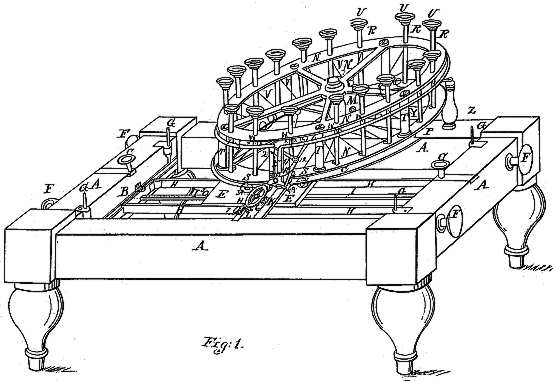
Figure No.1 represents a perspective view of the machine.
No.2 represents the center-bar 4, the semi-circular band O, which supports the rolls S, the ratch 3, the lever 7, and the small dog 14.
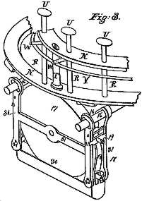
No.3 is a rear section of the machine, representing the box 30, which contains the ink, the scrapers 18, the regulating-screws 19, the roll 17, that wades in the ink, the frame 31, which supports the roll 17, a section of the horizontal wheel N, which supports and carries round the keys R upon which the types are fixed, the studs T, the ivory heads U, and a section of the frame A.
No.4 is the guide 2, the perpendicular, lever 15, the horizontal lever 7, and the lever 13 with which it is connected, and the dog 8.
No.5 is the rack 6.
No.7 is the ratch 3.
No.8 is the axis 4 and the pinion 5.
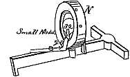
The figure over which is written.“Small Model” shows how, by another arrangement, the wheel N may be hung, so as to swing perpendicularly, and 20 represents how the horizontal lever may be made which turns the ratch.
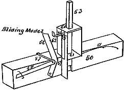
The figure over which, is written “Sliding Model” represents another arrangement for pushing the paper along, in which 50 is the stand to which the work is fixed, 51 is the key-spring; 52, the guide; 53, the key; 54, the steady-pin; 55, the slot; 56; the upright lever; 57, the lever spring; 58, the arm which pushes the paper along; 60 and 61, sections of the two rims of the wheel N.
 |
 |
The frame which supports the whole is made of wood or of metal, rectangular in form, (represented in the figure by A,) supported by four or more legs, the size of the frame varying with the size of the paper or the book upon which the printing is to be done. At each end of the frame and attached to its interior side, is a way, B, which rises or falls in obedience to a thumb-screw, C, which passes through a nut, at D, in each of the ways. When the ways are at the elevation required by the thickness of the book or paper which is to be put upon the platen, E, the ways may be made fast by the horizontal screws F passing through the frame, and pressing against the ways B or against the wires G attached to the ways B. The wires are put in merely to be guides to the ways in their ascent or descent, so that one end of the carriage H may not be depressed or elevated more than the other end.
Instead of making the ways so as to rise or fall in obedience to the set-screws, as described above, they may be fastened permanently to the frame, and the wheel which carries the type around, together with the apparatus for inking, may be made to rise and fall in proportion to the thickness of the paper or book which is to be printed. If the type are raised it of course leaves more room between the bottom of the type and the platen, and consequently a thicker book or paper could be placed upon the platen. It is immaterial whether the platen or the wheel with the inking apparatus be raised or depressed, as in either case the space between the platen can be regulated according to the thickness of the thing to be printed. As the printing will generally be done upon separate sheets of paper, there will be no necessity that either the ways and platen or the type with the inking apparatus should be made so as to rise or fall.
When it is rendered necessary by the nature of the thing printed, the object may be effected in either of the ways described above.
Instead of placing the ways B at the extreme ends of the carriage H, they may be placed under the carriage at some places nearer the center, on which the carriage H may move. These ways, when placed in the latter positions, may be supported at one end by the frame A in the rear, and the other end by the frame A in front. The carriage being necessarily twice the length of the platen, and of course twice the length of the book or paper, must necessarily sometimes be so long that if the ways were at its extreme ends it would not move so easily as if the ways were placed nearer its center. In such cases it may be found better to place them thus.
The carriage H is designed to move forward on the ways B as the type are successively pressed down upon the paper, and to move backward when pushed back to begin a new line. Its sides also serve as ways on which the platen moves when a new line is commenced.
The manner in which the carriage is moved when the type are thrust down upon the paper will be described hereinafter.
From one end of the carriage to the other, in the middle of it and passing directly under the center of the platen, is a flat piece of brass or other metal, I, which is an index to determine the distance which the lines are to be apart, perforated with rows of holes, (represented by the dots in the index or brass I,) the holes in each row varying in distance from each other, as the lines are to be more or less distance from each other. The lines of course must be more or less distant from each other, according to the size of the type with which the printing is to be effected. The spring J is fixed at or near the center of the under side of the platen, and passing along over the index I to the middle of one end of the platen, and turned up perpendicularly, so that it can be lifted easily by the hand: Underneath this spring is a sharp-pointed wire, i, the point of which snaps into each successive hole in the index as the platen is pushed along by the hand to form a new line. Across the carriage from side to side, and passing through its center or near its center, is a rack, K.
From the middle of one side of the frame to the middle of the other passes a solid bar, L, called a “center bar,” made of metal or wood. This is designed to support the wheel N, which contains the type, and the circular band O, which supports the rolls S and the guide Z, and also the ratch and horizontal lever, &c. From one part of this center bar rises a perpendicular arbor, M, on which a horizontal wheel, N, turns. A semicircular band, O, resting by its two ends on the frame at P, and by its center on the bar L, passes around directly under the type. This is intended merely as a support for the rolls S. Through this circular band two or more rolls B, protrude, on which the ink is carried by a process hereinafter to be described. By these rolls the type are inked. The rolls S are covered with deerskin, or the composition usually made use of by printers for their rolls, or by any other elastic substance which would properly transmit the ink to the type.
A horizontal wheel, N, made of brass or other metal furnished with two rims, turns upon the arbor M. This wheel is designed to carry around the type that they may be thrust upon the paper at their proper places. The rims are fastened together by the studs T. Through the rims of this wheel, equidistant from its center, the keys R pass, which have the type on their lower ends.
The keys containing the characters used in punctuation may be placed in the same circle or may be, placed so as to make a smaller concentric circle within and parallel to the circle formed by the letters. In the model they are all in one circle. The number of the keys will vary according to the number of letters used. One alphabet at least must be attached to the keys. If capital letters also are required the number of the keys must equal the letters in two alphabets. If the figures are required, ten more keys will be required, and so on, their number increasing with the number of letters or characters. On the upper ends of these keys are wooden, ivory, or metallic heads U. In the model they are made of ivory and of a shape suitable to put the fingers upon when the type are to be thrust down. On these heads are to be marked by engraving or otherwise the letter indicating the one on the lower end of the key.
The type to be used are the common type used in printing, soldered on the lower end of the keys in such a position that each letter, when stamped upon the paper shall make its impression in an exact line with every antecedent impression and exactly parallel to it. These type may be cut upon the lower end, as in the model, or they may be swaged on their lower end, or a hole may be drilled into the lower end of the keys, and the type inserted into these holes and made fast by melted sealing-wax. The sealing-wax when cool will keep the type firm in their holes.
There are but fifteen keys in my model, inasmuch as it was designed merely to show the principle.
At a point in the center bar, L, over which the type pass is a hole, Q, through which the keys and type when stamped on the paper are thrust. This hole should be so large that the type may pass through it and without marring the type against its sides. The keys R are raised and kept in the position which they are intended to occupy when at rest by springs V.
Instead of the springs used in the model spiral springs may be used, coiled around the keys between the two rims of the horizontal wheel N. The rims should then be sufficiently far apart to admit between them a spiral spring sufficiently long to bring back the keys. After the type have been thrust upon the paper pins are screwed into the body of the keys and at right angles with them, and pointing outward on a line and parallel with the radii of the wheel. These are screwed in at such a point of the keys that when the they are in the position they occupy when at rest, the pins shall strike the lower side of the upper rim of the wheel N, and the type shall rise just high enough to escape being inked by the little rolls S as the type pass over them.
To prevent the type and keys from turning around, wires X are made to pass through the upper rim of the wheel downward, so that one shall be on each side of the pins W, which are screwed into the keys.
Instead of small pins screwed into the key, as in the model, stronger and larger pieces of metal may be used, near one end of which holes may be drilled large enough to slip over the keys, and then small set-screws may keep them in their place, or they may be fastened in their position by soldering, or otherwise. A circular wire or rim, Y, is made to pass round the keys parallel to the circle formed by the keys, exactly horizontal and at such a distance from the keys outside that the steady-pins W can rest upon the circular wire Y when pressed upon by the finger, and at such a height that the type, when the steady-pins are pressed upon the wire, may pass over the rolls, pressing upon them sufficiently to ink them properly; This circular wire is supported by stud Z, set into the frame of the machine or any other convenient part.
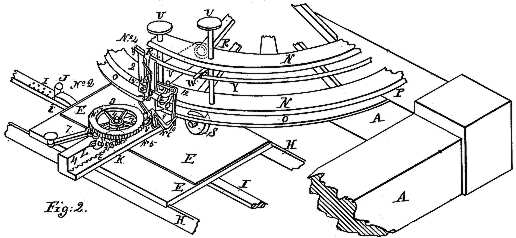
Directly in front of the wheel N is a flat piece of metal, called a “guide,” (represented by Fig. 2,) fastened to the central bar, L, and rising perpendicularly. A slot is cut in the middle of this flat piece of metal perpendicularly, and of sufficient width to permit the steady-pins W to pass down into it when the type are thrust upon the paper. The circular wire Y rests upon the top of this guide, and directly over the slot it is filed through, to permit the steady-pins to descend into the slot. Directly in front of the guide 2 is a ratch, 3. The axis of this ratch passes perpendicularly through the center bar, L, and on the lower extremity of the axis 4 is a pinion, 5, which gears into the rack 6, and as the ratch is turned one way or the other the carriage H, which supports the platen E, is moved backward or forward. Under the ratch, and turning on the same center as a fulcrum, is a horizontal lever, 7, which, when not in action, lies upon the center bar, L. A dog, 8, is fixed to this level at such a place that its ball play into the gear or teeth of the ratch, and as the lever is pushed on one side the dog throws the wheel around, and the carriage H is moved along for each successive type to make its impression on the paper in its proper place. The further extremity of the lever toward the wheel N turns at a right angle at the figure 9, and again at another right angle at the figure 10, the last part being parallel with the body of the lever. There is another angular lever, 11, turning upon a horizontal pin at 12, affixed to a branch, 13, of the guide 2, and in such a position that one arm may press horizontally against the further extremity 10 of the first lever, 7, and the other arm, 11, is so placed that when the keys are pressed down their steady-pins W throw down the arm 11 of the lever. The other arm, 13, presses against the first lever and the ratch is moved, and as a necessary consequence the carriage is moved. Another small dog, 14, fixed on the center bar, L, on the side of the ratch opposite the large dog 8, or at some other convenient place, plays into the teeth of the ratch and prevents the return of the ratch with the return of the first dog, 8. Each lever and dog is brought into position by springs. There is an upright lever,15, directly in front of the slot of the guide 2, and when a type is thrown down upon the paper, if that type is narrow and requires the paper to be thrown forward but a short distance, a longer steady-pin is put into that key, in the end of which this small type is placed, and then when the letter is thrust down upon the paper the long steady-pin comes out through the slot sufficiently far to push aside the upper end of this lever 15. The lower end descends at the side of the guide 2, so that the tail of the large dog 8 strikes against it while carrying the ratch around, and the dog is thrown out of gear so that it does not move the ratch, and consequently the paper, so far as for a large letter. By lengthening the lower end of the upright lever 15, and increasing the horizontal width of the steady-pin of any given letter on the side which strikes the upright lever it is evident that the lower end of the upright lever would be thrown down farther toward the extremity of the tail of the dog, and thus the dog would be sooner thrown out of gear in proportion as the steady-pin is increased in bulk on the side which strikes the upright lever. Thus the steady-pin of each key may be made by increasing or diminishing its length or bulk to throw the platen and paper along in proportion to the width of the letter.
In order to leave blank spaces between the consecutive words, the lever 7 must be moved toward the left by a horizontal pressure of the hand at the end nearest the operator.
Under that part of the circumference of the wheel N, opposite the guide 2, is the apparatus for containing and bringing up the ink. A double frame, 31, consisting of two pieces in the shape of an H is hung on the end of two bars at 16 by one end of each of the legs between these two frames, H, and hung by a horizontal axis passing through the center of the cross-bars of these two frames is a roll 17, which wades in a box of ink, 30, hung underneath the roll 17. This roll may be made of wood, or metal or covered with leather or composition. In order that too much ink may not be carried up by the roll 17, two scrapers, 18, are placed on opposite sides of the roll, which may, by the screw 19, be made to sit more or less near the roll and permit more or less ink to be carried up by the roll. Under the lower rim of the wheel N, and in the same circle of the type are some elastic cushions, 20, made of leather or composition, which, as the wheel N is turned around by the hand, pass over the roll 17, which bring up the ink and cover themselves with ink. Then as these cushions 20 pass around they deposit this ink on the small rolls S, which last rolls S ink the type as the type pass over the rolls. The wheel in which the type are set may be made to turn perpendicularly, as represented in the drawings. The key would then pass out through its circumference like the radii of a wheel. This last-mentioned key is represented by 32, small models. The lever 7, to which the dog 8 is fixed which turns the ratch 3, may be made the shape of the one in Fig. 20, and then the steady-pin of each key would throw the lever aside more or less, according to the thickness of the steady-pins. When a type is thrust down upon the paper by the above arrangement, the platen and paper are moved forward. If the platen and paper continued to move as long as the type continued to be pressed down it is evident the paper would continue to move after the type touched it, and the type would make a bad impression upon the paper. This difficulty must be provided for. The paper should cease to move just as the type is about to touch it. This object is gained, in the first way described above, by the tail of the dog 8 striking against the guide 2 or the lower end of the upright lever 15 and being thrown out of gear. It is thrown out of gear and ceases to turn the latch, and, consequently, to move the platen and paper just at the instant when the type is about to strike the paper. This object is gained in the second mode described by the shape of the horizontal lever, as represented by 20 of small model. When the pin first strikes the slanting edge of that lever, it throws it, aside; but after it reaches the straight edge at the moment the type is about to strike the paper it as evident it will throw it no farther.
The mode of moving the platen and paper is in part executed by a ratch; but in future machines it may be found convenient to dispense with the ratch and have an upright lever hung on the center-bar, L, in front of the guide 2, declining a little from the perpendicular toward its upper end. Two or three dogs hung to this upright lever in such a manner that one of them should be sure to push against one of the teeth of the rack 6, and then when the upright lever is pushed forward it would throw forward the rack 6, together with the carriage to which it is attached and the platen and the paper. By this last arrangement the rack 6 instead of having its teeth on one side must have them on its upper side or edge, so that the dogs can hitch into them. This upright lever standing just in front of the slot in the guide 2 would be hit by each steady-pin as each key is thrust upon the paper, and the upright lever would be thrown forward just in proportion to the length of the steady-pin. The object in having more than one dog is to make it certain that one shall hit some tooth in the rack 6 every time the upright lever is thrown forward.
The last twenty-eight lines may be more particularly explained by reference to the representation on the drawings by the words written over it, "Sliding Model." 50 is the wooden stand corresponding with the center piece, L. 56 is the upright lever. 57 is the spring bringing it back into position. 58 is an arm, the end of which presses against the teeth of the rack and pushes the platen forward. 52 is the guide corresponding to the guide 2 in drawing No. l. 55 is the slot in the guide. 60 and 61 represent sections of the upper and lower rim of the wheel N in drawing No.l. 53 is a key. 54 is its steady-pin. Pressing down the key 53 causes its steady-pin 54 to strike against the upright lever 56 and pushes it forward, and the arm 58 is necessarily pushed forward, which arm pushes the rack and platen forward. When the pressure is taken from the key 53, the spring 51 throws it up again, and the spring 57 brings back the upright lever 56. Instead of the spring 51 a spiral spring coiled round the key will be preferable. I call this the “sliding model” because it may be used for sliding the carriage and platen forward. In this arrangement the movement of the paper ceases just as the type is about to be pressed on the paper by the following contrivance:
When the key 53 is pressed down so far that its steady-pin 54 arrives at that point of the upright lever at 59, it is evident that although the key may be pressed down a little farther it will not throw the upright lever 56 any farther forward. The steady-pin at its external end must have such a perpendicular thickness that when it is pressed, beyond the point 59 some part of its end may still lie against 59, so as to prevent the return of the upright lever 56 till the key 53 rises again.
To prevent the keys and of course the type from turning round in their places, wires X, as described above, pass through the upper rim, one on each side of each steady-pin; but in machines hereafter to be made a band may be put around the horizontal wheel N and fastened to the external edge of its rims, reaching of course from the upper to the lower rim. This band, it will be readily seen, instead of being fastened to the rims after the wheel N is cast, may be cast upon it, and the upper rim instead of being connected with the center by arms, as in the figure and model, may be supported simply by this band. Through this band perpendicularly slots must be cut in front of each key from the upper to the lower end to permit the steady-pins of the keys to pass through to prevent the keys and type from turning. These slots should be just wide enough to permit the steady-pins to pass up and down.
To use this machine, the first thing to be done, is to whirl round the horizontal wheel N till the ink is properly distributed. The paper is put upon the platen and the platen is to be moved till that part of the paper where the printing is to commence, shall come directly under the hole in the center bar through which the type pass when thrust upon the paper. Then put the finger on the head of the key which has the letter which is first to be used. Press it down until its steady-pin touches the circular wire Y. Slide the key upon the head of which the finger is put toward the guide 2 until it is thrust, by the pressure of the finger upon the paper. At the end of the word push the lever to the left, as before described, as far as is necessary to leave the space between the words and then put the finger upon the next key-head, which is wanted to begin the next word. When a line is ended, whirl the wheel N around to get fresh ink. Raise the spring J, which passes under the platen by lifting it up by the hand. Push the platen along till the wire in this spring snaps into the next notch or hole of the index for another line. Throw the carriage backward and proceed as before.
The rolls S, which immediately feed the type, and the cushions 20 should be frequently cleansed by a solution of pearlash and water, or some other alkali.
What I claim as my invention, and desire to secure by Letters Patent, is –
1. The combination of the movable carriage H and the platen E with the wheel N containing the type, substantially in the manner and for the purpose as herein set forth.
2. The employment of the wheel N, having a set of keys around its periphery on which are type for printing, constructed and arranged substantially as herein specified.
3. The employment of the ratchet-wheel, pinion, and rack in combination with the keys and pawl for forcing forward the carriage, and also in combination there with the lever 15 for shortening the distance the carriage has to move.
4. The combination of the guide and wire Y with the keys for regulating their motion, all as above described.
5. The inking apparatus in combination with the wheel of type N, arranged in the manner and for the purpose hereinbefore made known.
6. In combination with the above described apparatus, the employment of movable ways for elevating, and depressing the carriage, substantially in the manner set forth.
CHARLES THURBER.
Witnesses:
LEWIS T. LAZELL,
ENOS DORR.
- 2 Jan - short biography, births, deaths and events on date of Thurber's birth.
- More for Charles Thurber on Today in Science History page.
- Charles Thurber - Printing Machine (Typewriter) Patent No. 3228 - Brief Descriptions.
- Large picture of Charles Thurber Printing Machine (1000 x 700 px)
- Thurber’s Chirographer - his second machine, described in article from Scientific American (1847)
- 26 Aug - event description for date Patent No. 3228 (issued 26 Aug 1843), and other events.
- Typewriter Quotes - Today in Science History