
|
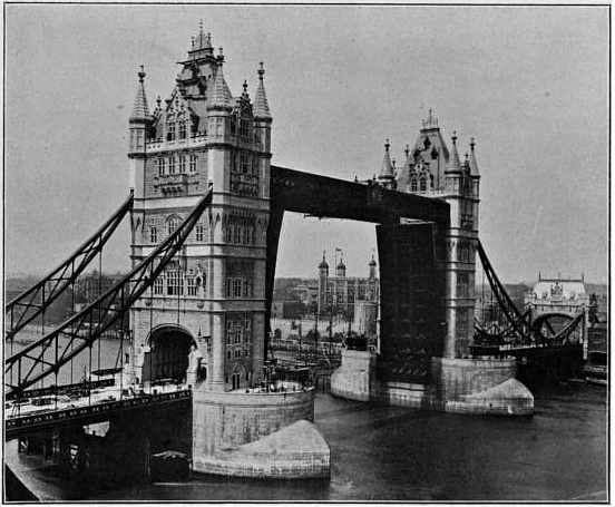
The Tower Bridge
(Foundation stone laid 21 Jun 1886)
The iconic bascule bridge across the
River Thames in London, which was officially opened on 30 Jun 1894.
|
The Tower Bridge.
by Archibald Williams
from The Romance of Modern Engineering (1908)

A notable feature of the structure is that the ironwork is quite independent of the masonry, which is out of contact with the real supports, concealed inside.
The foundations of the two towers are capable of supporting without settlement, a weight of 70,000 tons.
LESS imposing as a structure than the giant conqueror of the Forth is the new bridge that spans the Thames, a short distance east of the Tower of London, from which it derives its name.
The Tower Bridge is, however, of such importance and interest, both on account of the problems that it has solved, and from the manner in which it has solved them, that this great framework of metal and masonry, so familiar to the Londoner, deserves inclusion among the chief engineering feats of modem times.
The general outlines of the Bridge, being so well known, need little detailed description. Technically, it is a three-span bridge, the two outside spans of the suspension type carried on stout chains that pass at their landward ends over abutment towers of moderate height to anchorages in the shore, and at their river ends over very lofty towers, themselves connected at an elevation of 143 feet above high-water level. Extremely powerful ties, borne on the connecting girders, unite the two pairs of chains, making the suspension spans to support one another in a horizontal direction.
The central span has two footways and one road. way. The high-level girders bear the upper footway, reached by two hydraulic lifts situated in each of the main towers.
The most notable feature of the Bridge, unless we except the unique combination of steel and masonry work in the towers, is the method of enabling traffic, pedestrian and vehicular, to cross the 200-foot space between the towers, at the level of the roadway of the two outer spans. History repeats itself in engineering as elsewhere, and, as an example, we see here a reversion to the idea of the drawbridge that shut off the mediaeval fortress or town from the hostility of the outside world. Principle apart, however, it is a far cry from the wooden platform, heaved laboriously aloft by creaking chains, to the massive 1200-ton steel leaf raised noiselessly by the unseen energy of hydraulic engines.
Before entering into details of construction, it will be interesting to glance for a moment at the antecedents of this latest-born of Thames bridges—the reason for its erection, and the considerations that cast it into its present form.
Let the reader take a map of London and fix his eye on Blackfriars Bridge. A line drawn due north and south through the bridge would approximately bisect the metropolis. A steamboat travelling westwards from this point passes in succession under Waterloo, Westminster, Lambeth, Vauxhall, Chelsea, Albert, Battersea, Wandsworth, and Putney Bridges—nine in all—open to vehicular traffic. On an eastward journey of equal length it would, however, have to lower its funnel for but two—the Southwark and London—assuming the Tower Bridge to be still in the future. Yet both banks are thronged by some of the most densely-populated districts of London, so near each other and yet so far for want of means of communication.
A further reference to the map shows us why things should be so. This is a region of docks and wharves, the latter reaching up to London Bridge, from which we have often watched the unloading of cargoes.
The engineer, called in to effect a compromise between the crying needs of road traffic on the one hand and the equally important interests of river traffic on the other, is able to suggest several methods of cutting the Gordian knot:
2. A high-level bridge, with inclined road approaches.
3. A high-level bridge, with hydraulic lifts at each end.
4. A tunnel under the river, with inclined approaches.
5. A tunnel with hydraulic lifts at each end. 6. A ferry.
Of these the first would be most convenient for the landsman, but most inconvenient for the sailor. The second and fourth necessitate very costly approaches, the third and fifth continual blocks in the traffic; and as regards ferries, they are at best but very poor substitutes for a bridge.
Among the many plans submitted since 1867 for a bridge, one is particularly noticeable for its originality—that of Mr. C. Barclay Bruce. He proposed a rolling bridge, to consist of a platform 300 feet long and 100 wide, which should be propelled from shore to shore over rollers placed at the top of a series of piers 100 feet apart. The platform would have a bearing at two points at least, and, according to the designer's calculations, make the journey in three minutes, with a freight of 100 vehicles and 1400 passengers. Another engineer, Mr. F. T. Palmer, proposed a bridge which widened out into a circular form near each shore, enclosing a space into which a vessel might pass by the removal of one side on rollers while traffic continued on the other side. As soon as the vessel had entered the enclosure the sliding platform would be closed again, and that on the other side be opened in turn.
In 1878 Sir Joseph Bazalgette, engineer to the Metropolitan Board of Works, recommended the construction of a bridge that should give a clear head-way of 65 feet above Trinity high-water level, but a Bill brought into Parliament for power to build it was thrown out on the ground that the headway would be insufficient, and on account of the awkward special approaches.
To avoid wearying the reader with a list of projects we will pass straight on to that of Mr. Horace Jones, the late City architect, who in 1878 was asked to report upon the various projects of Sir Joseph Bazalgette and make suggestions on his own account. He maintained that, as a high-level bridge would not give satisfaction, a structure of the same level as London Bridge, opening at the centre by means of hinged platforms, or bascules, might be advantageously employed. From his design has sprung that of the Tower Bridge—the joint work of him and Sir J. Wolfe Barry—which provides a central opening of 200 feet clear and a headway of 135 feet. An Act for its construction having been passed in the autumn of 1885, contracts were let for the foundations of the piers and abutment towers up to the level of 4 feet above high-water mark. On June 21, 1886, the (then) Prince of Wales laid the foundation stone.
The masonry piers on which the main towers stand are remarkable for their size—100 a feet wide by 205 long—which exceeds that of any in the world, with the exception of those of the Brooklyn Bridge. The piers being but 200 feet apart, the engineers, who were under agreement to leave a clear way of 160 feet between them, could not build both simultaneously as a whole, since the scaffoldings would have narrowed the opening beyond legal limits. They therefore adopted a system of small caissons, which should be sunk so as to form a broad wall round the area of the pier, and enclose a space of 34 by 124� feet, to be dealt with as soon as the exterior caissons were in position.
On the north and south sides of each pier four caissons were sunk, 28 feet square and 21 feet apart, each end of the rows being joined by a triangular caisson. While one pier was in course of construction, the shoreward row of caissons for the other pier was also sunk, thus saving time without obstructing the river.
Reference has been made in the previous chapter to the sinking of caissons; so it need here only be stated that at the Tower Bridge no pneumatic caissons were employed, but only the open variety. Divers cleared away the gravel and mud until a caisson had descended such a distance into the stiff London clay at which it was thought safe to pump out the water at low tide, and then navvies were turned in with pick and shovel. At a depth of 19 feet the caissons were undercut, i.e. the workers burrowed beneath their lower edges into the clay for a distance of 5 feet horizontally, and 7 feet vertically. The undercutting proceeded in sections—filled with concrete in succession—so that the caisson should not be left unsupported. When all the ten external caissons had been sunk and filled in, the narrow spaces between them were also filled, and the interior enclosure pumped dry and excavated. Finally, there emerged from the water a couple of gigantic piers of concrete, granite, and bricks, able to withstand without settlement a load of 70,000 tons. Their cost was � 111,122.
The contract for the steelwork in the superstructure was let to Sir William Arrol & Co., of Glasgow, who, as the reader will remember [from a previous chapter], had already taken an important part in the construction of the Bridge.
Before any metal-work could be placed in position, it was necessary to erect stagings from the shore abutments to the centre piers. This work occupied some months, and when it was completed operations at once commenced on the main towers.
Each tower consists of four octagonal columns, connected at a height of 60 feet above the piers by plate girders, 6 feet deep, across which are laid smaller girders to carry the first landing. Twenty-eight feet higher is the second landing, similarly constructed, and above that, at an equal distance, the third landing leading to the high-level footway. The columns each rested on massive granite slabs previously covered with three layers of specially prepared canvas to make the pressure even and the joint water-tight. They were keyed to the bed-stones by great bolts built into the piers.
The first length of column plates having being riveted in position by hydraulic riveters, the second length was added by means of a crane placed on the piers, and when the crane had been raised aloft on special trestles the third length followed. The first landing served as a platform from which to build upwards in like manner to the second, which in turn became the base of operations. All four columns in each tower were braced diagonally to resist the wind pressure—calculated at a maximum of 56 lbs. to the square inch, or several times greater than has ever been registered in that locality.
The columns finished, and the top landing girders in position, the workmen attacked the high-level footway. This was built out from both towers simultaneously on the overhang principle. First, the portions of the cantilevers immediately over the towers were erected and anchored to the shoreward columns. Then cranes were placed on the completed portions and moved forward to add fresh plates until the cantilevers had reached the point where the central suspended girder began. As at the Forth Bridge, this was built on to the cantilever ends, to which it was attached by temporary ties, and when the centre plates had been made secure, the ties were cut, allowing it to ride free at each extremity. Throughout the construction of the upper footway the greatest care had to be observed to prevent rivets, fragments, and tools falling into the river below to the peril of passengers on passing vessels.
Along the upper boom of the footway run the great ties connecting the suspension chains at their river ends. Each of the two ties is 301 feet long, and composed of eight plates 2 feet deep and 1 inch thick, terminating in large eye-plates to take the pins uniting them to the suspension chains. The construction of these chains was one of the most interesting and at the same time most delicate parts of the whole undertaking. Each chain is composed of two parts, or links; the shorter dipping from the "top of the abutment tower to the roadway, the longer rising from the roadway to the summit of the main tower. The links have each a lower and upper boom, connected by diagonal bracings so as to form a rigid girder. They were built in the positions they had finally to occupy, supported on trestles, and were not freed until they had been joined by huge steel pins to the ties crossing the central span and to those on the abutment towers. In order that the reader may have a clear conception of the action of the ties and chains, we will personally conduct him from end to end of the series. At the north end of the bridge is a huge mass of concrete surrounding an anchorage girder 40 feet long, 4 feet wide, and 4 feet deep, to which is attached a land tie springing up to the shore edge of the abutment top. At the anchorage end the tie is joined by a pin, 2 feet in diameter, to the girder, and at its upper end to the horizontal links crossing the abutment tower. The tie is built up of twelve plates 21 inches wide and nearly an inch thick. The link plates are 5 to 5� feet wide and 7/8 inch thick and 22 feet long. At each end they rest on roller bearings moving over 3-inch steel plates very carefully levelled. Then comes the short link of the chain, attached by eye-plates and a steel pin, 2� feet in diameter, to the tie and also to the lower end of the long link, at which point both are joined to the girders of the roadway. Passing up the long link we reach the top of the towers and note the great pins and roller bearings at each end of the 301-foot ties. Then down the south long link to the roadway, up the short link, and over more roller bearings to the last section of the series—twelve plates 35 inches wide secured by rivets to the south anchorage girder, which is of larger dimensions than its northern fellow. This arrangement of chains, links, and ties permits a slight amount of horizontal motion to compensate the stresses of unequal loading on the two suspension spans, and the alterations in the length of the metal connections in varying temperatures. Roller joints are also made in the flooring of the side spans at each end and at the junction of the links to allow for longitudinal expansion and contraction.
The boring of the pin holes was a matter of great delicacy and considerable difficulty. The holes in the eye-plates of ties and chains had been cleared to within half-an-inch of their final diameter before leaving the contractor's works at Glasgow, and the finishing touches were added when the plates were in position. The labour of expanding out the holes to their full diameter was equivalent to boring a hole 2 feet 6 inches in diameter through 65 feet of solid steel; and most of this boring had to be done in somewhat awkward positions at the top of the main towers and abutments, whither it was necessary to transport engines, boilers, and boring tools. The fixing of these generally occupied as long a time as the actual boring, since the greatest accuracy had to be observed throughout the process.
The roadway of the suspension spans is carried on cross girders, 61 feet long, weighing 22 tons. At each end they are connected by 6-inch pins to the suspension rods hanging vertically from the chain links. The rods are from 5� to 6 inches in diameter, and furnished with a screw-coupling at their centres to enable the accurate adjustment of the girders to the true level of the roadway. Before leaving the works each rod had been subjected to a tension of 200 tons, so that of their sufficiency there can be no doubt. Longitudinal girders of smaller section were then laid on the transverse girders, and on these again corrugated floor plates, afterwards filled up with concrete to form a slightly convex surface, over which wood paving blocks were placed.
We may now turn our attention to the central span of the roadway, which forms, perhaps, the most interesting part of the whole structure.
Each bascule, or leaf, of the drawbridge consists of four parallel girders, 131 feet apart, and about 160 feet long. When lowered it projects horizontally 100 feet towards the opposite tower, spanning exactly half of the opening. The point of balance is a solid pivot, 1 foot 9 inches in diameter and 48 feet long, that passes through the girders 50 feet from their shore ends. The pivot is keyed to the girders, and rotates on roller bearings carried by eight girders crossing the piers horizontally from north to south, themselves borne on girders under their ends.
The chief difficulty attending the erection of the bascules resulted from the condition compelling the contractors to leave a clear way of 160 feet between the towers. Under other circumstances the girders might have been completed before being brought into line and connected together. As it was, the engineers first built the portions on the shore side of the pivot, added a short section of the river side steelwork, and launched the incomplete girders from the main stage close to the piers into the bascule chambers. A temporary steel mandrel was inserted to carry their weight while they were turned into a vertical position, and then withdrawn to make room for the permanent pivot, weighing 25 tons. The outer ends were added to until a point 53 feet from the pivot had been reached, and work in this direction then stopped until the raising and lowering of the leaves for purposes of adjustment had been concluded; after which the girders were completed vertically.
The leaves are moved by means of pinions (or cog-wheels) engaging with racks fixed to the edge of two steel quadrants riveted to their two outside girders. The accurate attachment of the racks was a some-what difficult business on account of the confined space in which the men had to work.
To preserve the balance of the bascule it was necessary to load the shorter, or inner, arm with counter-poises, consisting of 290 tons of lead and 60 tons of iron enclosed in ballast boxes at the extreme ends of the girders. The function of the raising gear is merely to overcome the inertia of the 1200 tons of the leaf, and the friction caused by wind pressure on the exposed surface. In designing the hydraulic machinery allowance was made for a wind pressure of 56 lbs. to the square foot, which would produce a force of 140 tons acting with a leverage of 56 feet.
The source of power is a building on the east side of the southern approach, where are stationed two large accumulators with 20-inch rams loaded to give a pressure of from 700 to 800 lbs. per square inch. An accumulator is the hydraulic counterpart of the reservoir bellows in an organ. It ensures a steady pressure, as its capacity is greater than that of the engines it operates; and since the pumping engines can be constantly at work filling it, there is always a plentiful supply of energy stored against the periodical opening and shutting of the bascules. The water is led through two 6-inch pipes, provided with flexible joints at points of movement, to the two sets of engines on the south pier; and to those on the north pier through continuation pipes passing up the south tower, across the footway, and down the north tower. After use, the water is returned through a 7-inch pipe to the pumping engines placed in two of the arches forming the southern approach to the bridge.
The engines are duplicated on each pier to avoid the inconvenience that would result from the breakdown of a single installation. The power of the engines is transmitted to the racks through a series of cog-wheels, which increase the effective pressure of the pistons almost sevenfold. Hydraulic energy is also used to work the two hydraulic lifts in each main tower, and to shoot home and withdraw the four locking bolts at the outer extremity of the southern leaf.
In this connection the following extract from Mr. J. E. Tuit's fine book on the bridge will be of interest. "Every precaution has been taken so that the operation of opening and shutting the bridge shall be rendered as safe as possible. By an automatic arrangement attached to the hydraulic engines on the piers they are caused to close the valves which admit the high-pressure water just at the end of the operation of raising or lowering the leaves, so that even if the man in charge were to make a mistake through an error of judgment, or be prevented from attending to his duties, the leaves would gradually bring themselves to rest either in a vertical or horizontal position without the least chance of any catastrophe. As a still further precaution, however, hydraulic buffers are fixed in such positions that if the men in charge lost control of the bridge, and at the same time the apparatus above alluded to for bringing up the motion of the leaves were to fail, their impact would be taken by these buffers, which would bring them to rest in the same manner as that in which the hydraulic cylinders that are attached to heavy guns take up the recoil."
In cabins at the east and west ends of each pier are indicators to tell the men in charge whether the accumulators are full before starting the engines, and whether the locking bolts are in their proper position. Further provision is made to prevent the raising of the bascules before they are cleared of traffic. The policemen in charge have to stretch a chain across the entrance to each pier. As soon as the chain is fixed, the man carrying it will be able to turn on the water to a small cylinder that draws it tight and at the same time releases the locking arrangement of the levers in the cabin. So that until the chain has opposed a barrier to the traffic, it is impossible to draw the locking bolts at the centre of the span.
The masonry of the towers is independent of the steelwork that it encloses. In fact, great care has been taken that there shall be no adhesion between the two substances. This part of the structure, carried out by Messrs. Perry & Co., calls for no special attention here, though it impresses itself favourably on the eye of the spectator. Objections have been raised to the external masonry on the ground that it is a "hollow sham," but we fancy that were the covering suddenly stripped away, so as to expose the steel skeleton beneath, many objectors would be silenced. The general opinion is that with so many metal structures exposing the nakedness of their outlines the London Corporation is to be congratulated on having thus boldly made a concession to the aesthetic tastes of the community which does not detract from the value of the bridge as a utilitarian erection. The cost of construction was enhanced, but the result is one of which Londoners will be proud in years to come.
The Tower Bridge, typical of modern engineering skill, has an interesting connection with the old London Bridge—itself a mechanical triumph considering the science of the time—built towards the end of the twelfth century. That bridge, which stood the wear and tear of nearly 700 years, was endowed with certain lands which, with the growth of London, became extremely valuable, and are now known as the Bridge House Estates. The revenue from them has enabled the Corporation of London to rebuild the London Bridge, throw another across the Thames at Blackfriars, and also to construct the subject of this chapter.
We may conclude the account by a few figures. The bridge is exactly half a mile long, including the approaches, the side spans each occupying 270 feet clear. Its extreme height, measured from the bottom of the foundations to the summit of the main tower ridge-tiles, is 293 feet. The roadway of the side spans is 35 feet wide, flanked on each side by a 121-foot paved footway. In the central span the widths are reduced by 3 and 4 feet respectively. Its construction, which occupied eight years, consumed 235,000 cubic feet of granite and stone, 20,000 tons of cement, 70,000 cubic yards of concrete, 31 million bricks, and 14,000 tons of iron and steel. The columns on the main piers and abutments required five miles of steel plates.
The total cost was estimated at three-quarters of a million pounds, of which the bridge itself represents rather more than half a million.
Sir J. Wolfe Barry, the engineer responsible for the construction, includes among his other important works the great Barry Dock near Cardiff, and the completion of the Inner Circle Railway between the Mansion House and Aldgate stations.
 21 June - short
biography, births, deaths
and events on date of laying the Tower Bridge foundation stone.
21 June - short
biography, births, deaths
and events on date of laying the Tower Bridge foundation stone.
")


